I’ve been wanting to make my pieces more consistent, so I decided to try my hand at making 3D printed pottery ribs. I’ve never actually used shaping ribs in my own process before, so I am not super familiar with how to design the shape properly. I am still in the iterative process of refining that. However! The CAD-ing process will remain relatively the same, so I will detail my own steps here. Please feel free to use this as a guide and remix on it. Tag me on Instagram (@jmks.goods) if you do!
For this tutorial, you will need:
- A sketch of your rib design
- A laptop that can run FreeCAD
From sketch to SVG
As mentioned above, you will need a sketch of the rib you want to make. The first step is to turn this sketch into an SVG file so that we can import it into FreeCAD. There are multiple ways of doing this, but my personal favorite is to just automatically convert my sketch into SVG using Inkscape.
In Inkscape, import your sketch, resize it using the Transform tool, then click on Path -> Trace Bitmap to convert your design into vector paths.
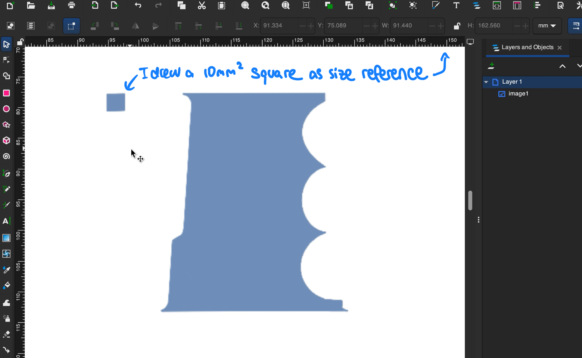
One trick I like to do (in order to control the size of my piece) is to draw a 10mm by 10mm square as reference. Then, I use the rulers at the top and left hand side of the window to resize the imported image so that the square is the size I want. After converting to SVG, you can delete the square.
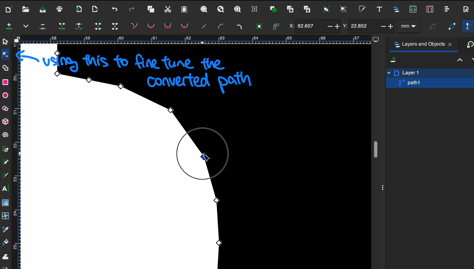
The additional benefit of using Inkscape (or any other vector graphics editor) instead of an online conversion tool is that you can fine tune the converted path:
However, if you want full control over the shape/dimensions, you can also just directly create the SVG in Inkscape. I don’t always do this because the 3D printer is not a very precise tool anyways (at least mine isn’t lol), so imperfections don’t matter too much.
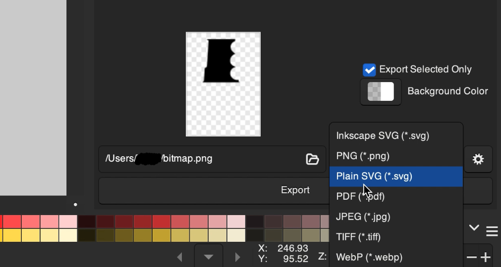
After you are done and happy with your rib design, export it to plain SVG.
Modeling in FreeCAD
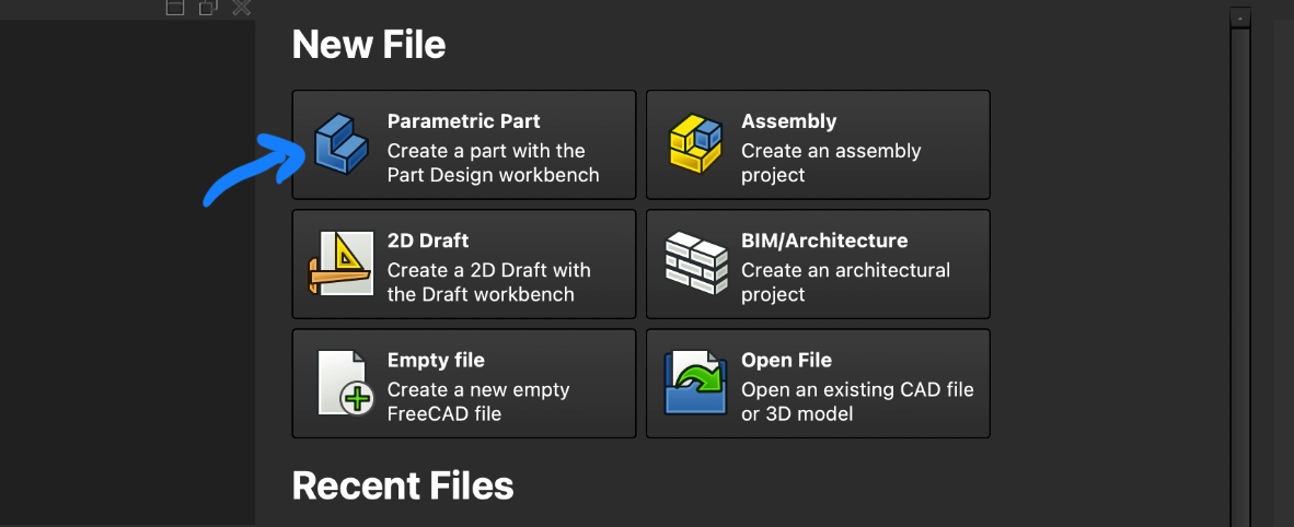
First, create a new Parametric Part.
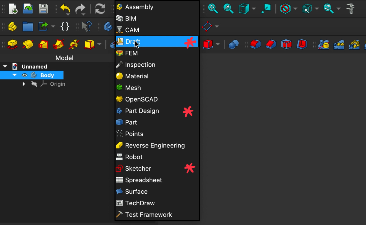
One thing to note about FreeCAD is that it uses workbenches that you can access through a dropdown menu. I’ve noted the ones we will be using with a red asterisk below. If you can’t find any of the tools we will be using in this tutorial, make sure that you are in the correct workbench first.
Converting to a sketch
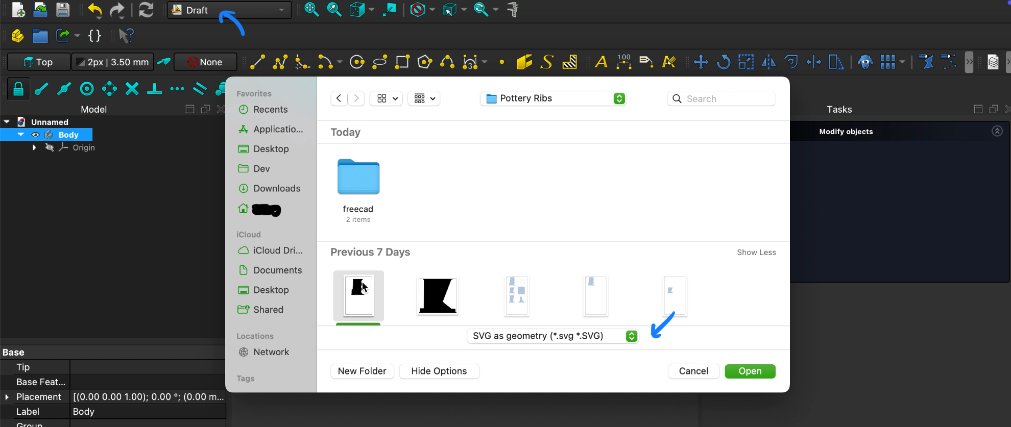
Go to the Draft workbench and import your SVG file:
Find your imported file under the Model window. With it selected, click on the Draft to Sketch button in the toolbar. You may have to expand the toolbar to find it:
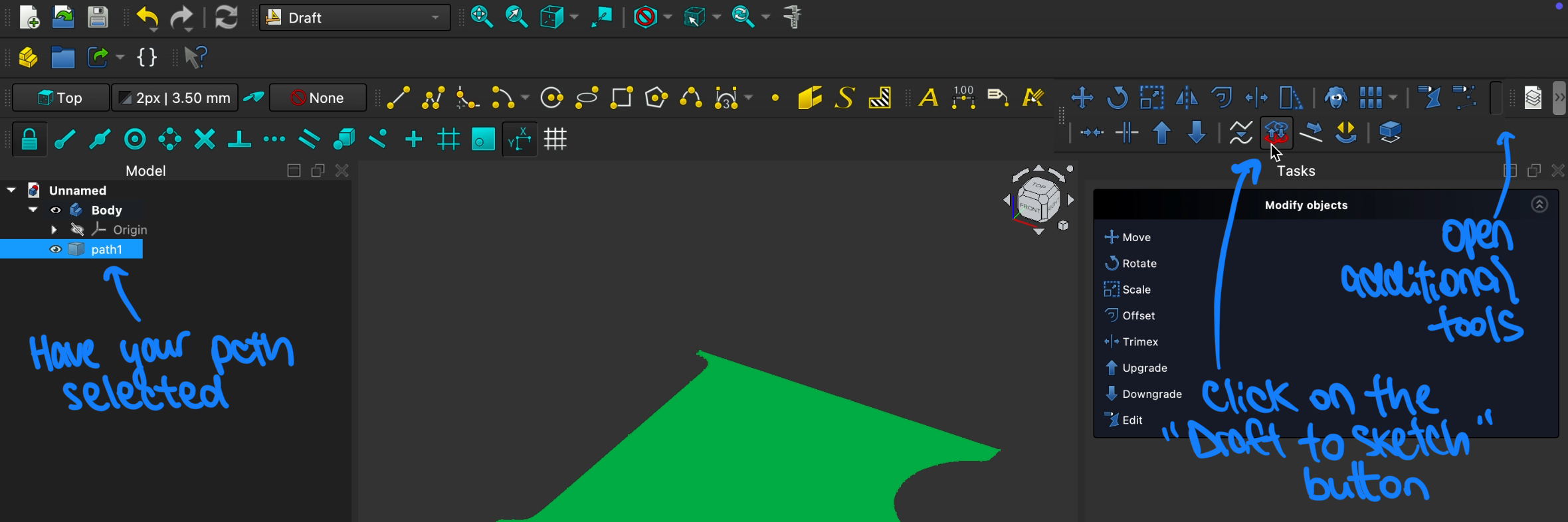 Now, your imported file (path1 in my screenshot above) can be deleted from the Model window.
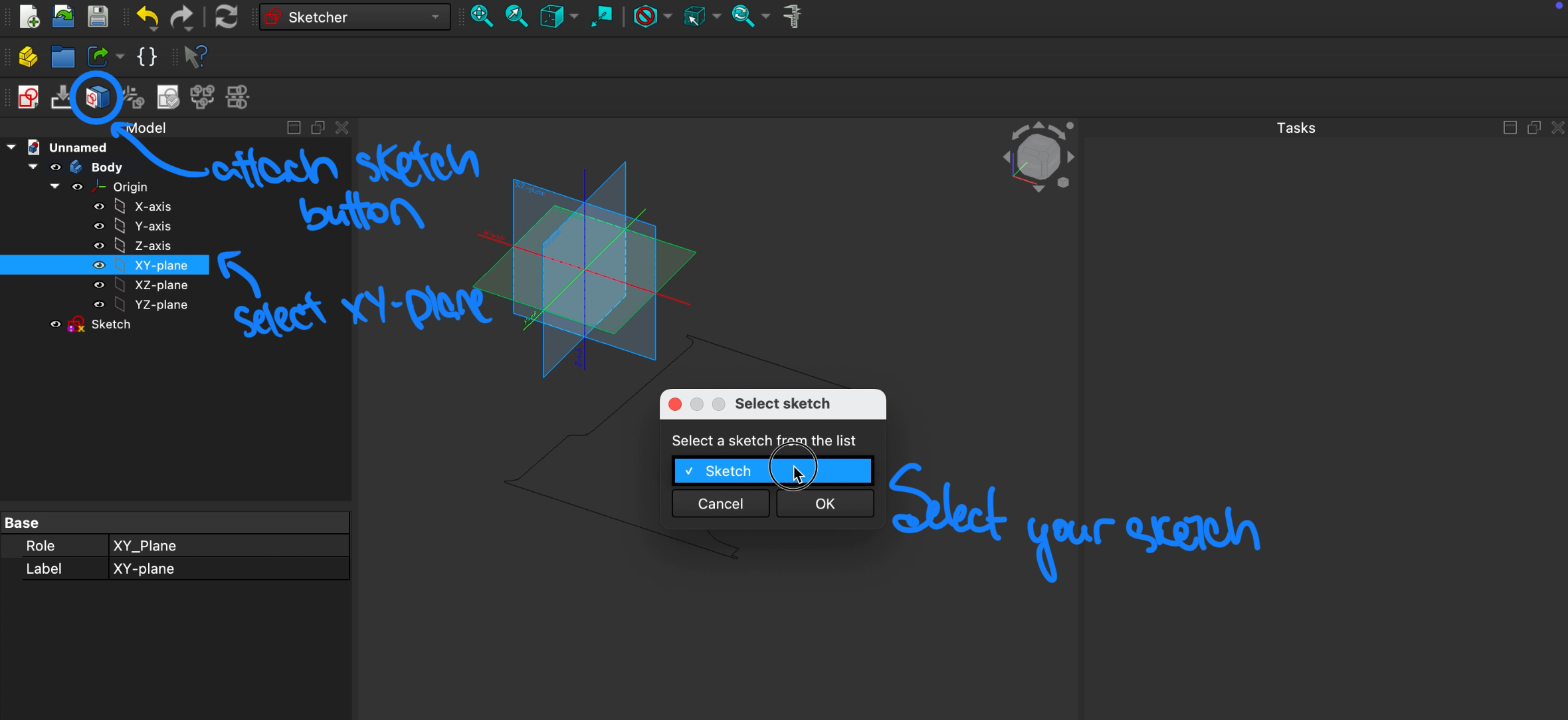
Next, go to the Sketcher workbench and select the XY-plane. Click on the Attach sketch button and choose your convrted sketch from the list. There should only be 1 sketch for now. Basically, what we are doing here is to give a point of reference (the XY-plane) to our sketch. Otherwise it would be floating in space.
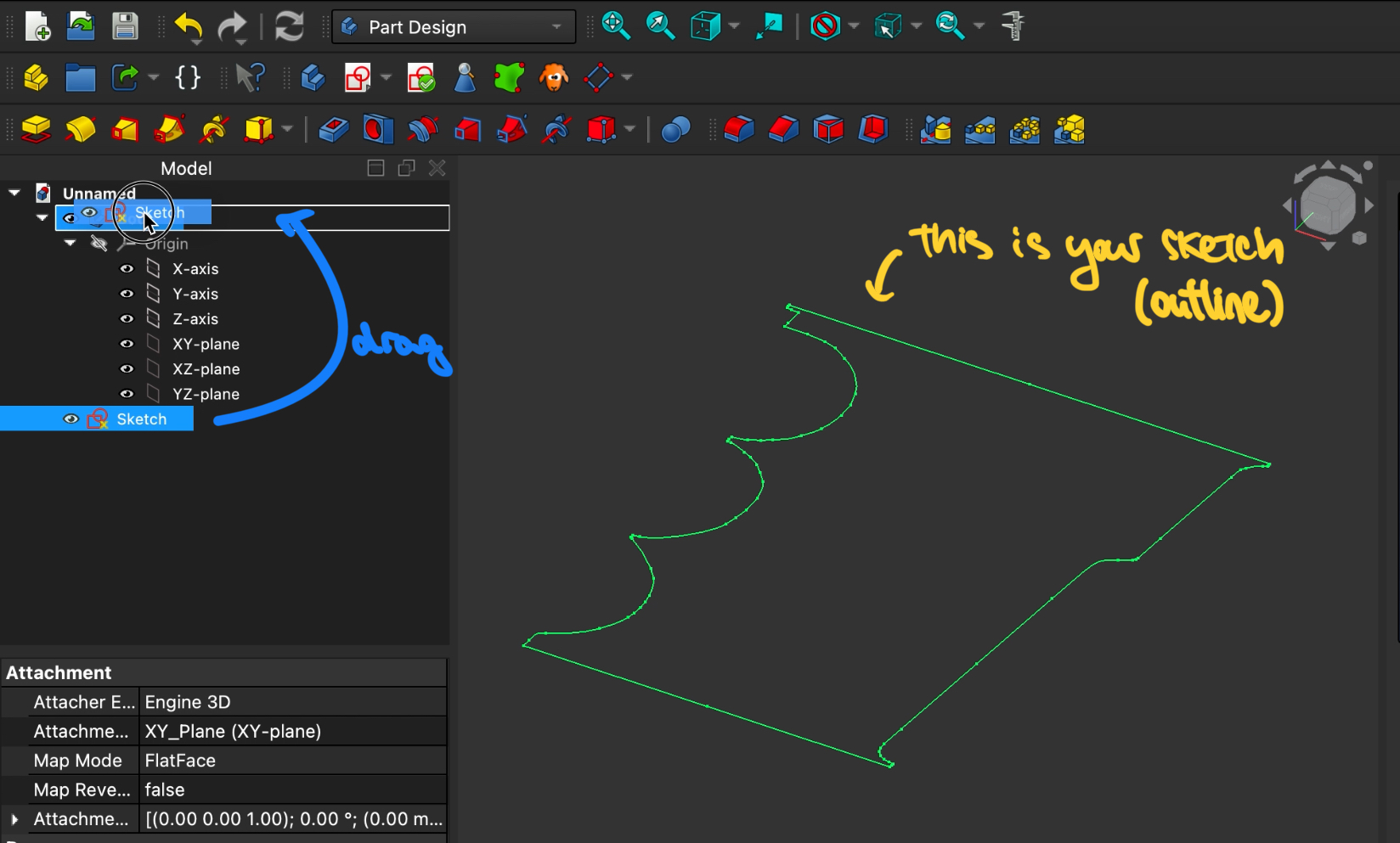
To give our model a 3rd dimension, go to the Part Design workbench. Drag and drop the sketch into the Body in the Model tree so that it is part of the object we are designing.
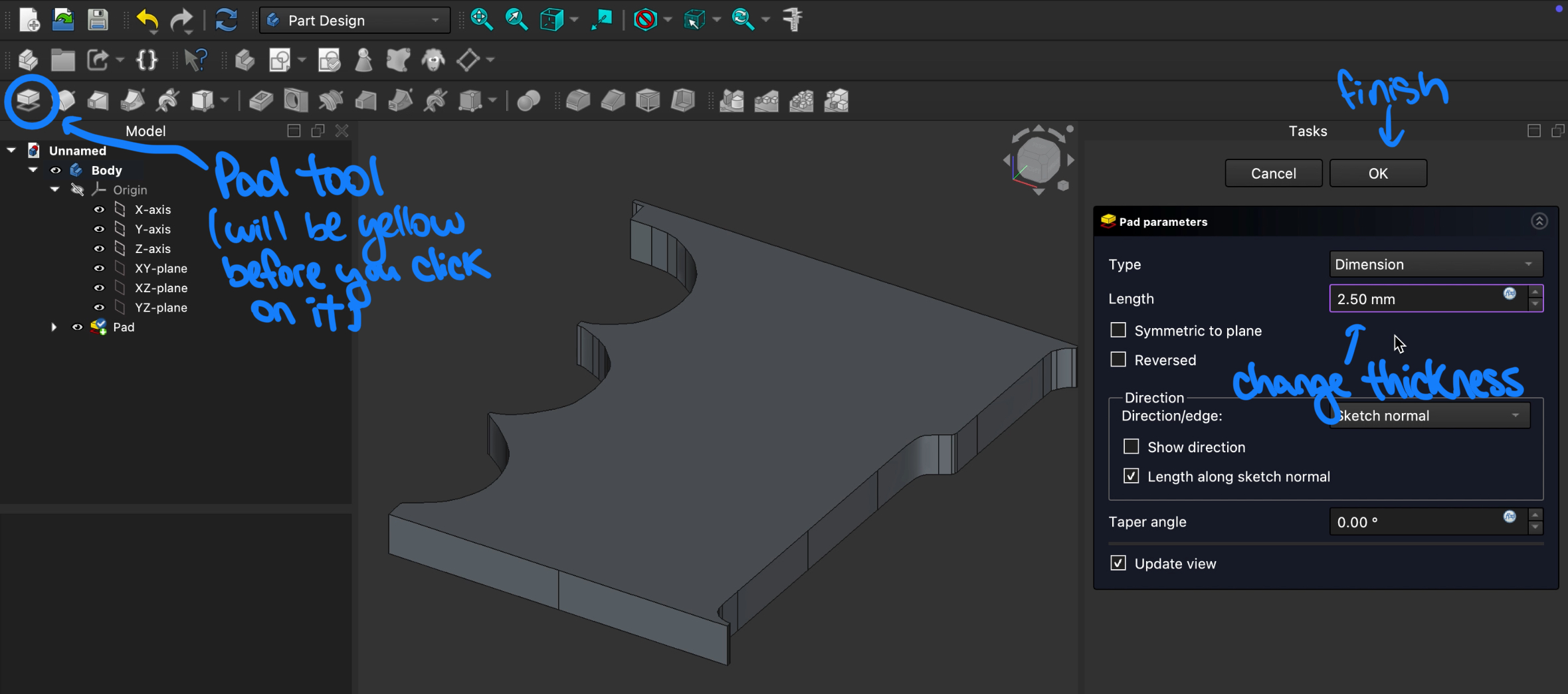
With the Sketch selected, click on the Pad button in the toolbar and edit its length to 2.5mm (or whatever thickness you want the rib to be).
The body is done! You can stop here now and skip to the export step, but I like to add thumbholes for a better grip on the rib.
Adding holes for grip
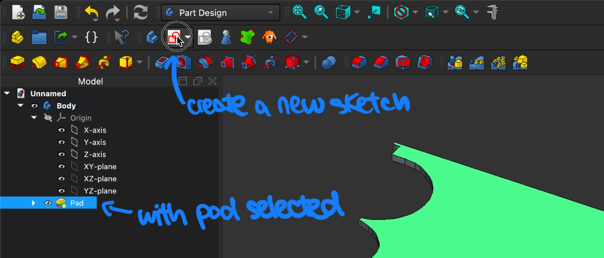
Now, we want to create another sketch on the newly created model for where we want the holes to be. Unlike what we did previously, instead of importing a sketch, we will be drawing it directly in FreeCAD.
To do this, with the model (Pad) selected in the model tree, click on the Create a new sketch button. This will take us to the sketcher workbench automatically.
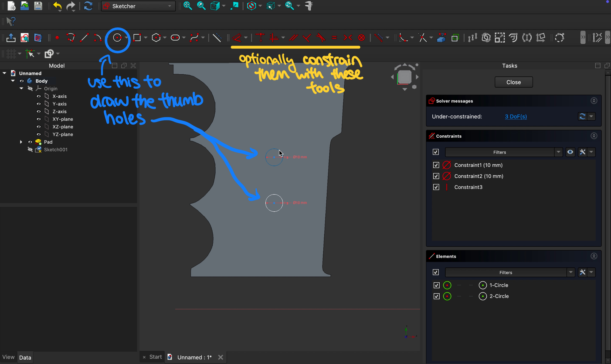
Click on the Circle button and draw hole(s) where you want them to be. I added 2x 10mm diameter holes in the middle of the rib. You can also add constraints to the spacing (such as the distance between the holes, distance to the edge, vertical alignment, etc.) using the constraints buttons in the toolbar which I’ve underlined in yellow. However, this is not super necessary functionality-wise, just makes it neater.
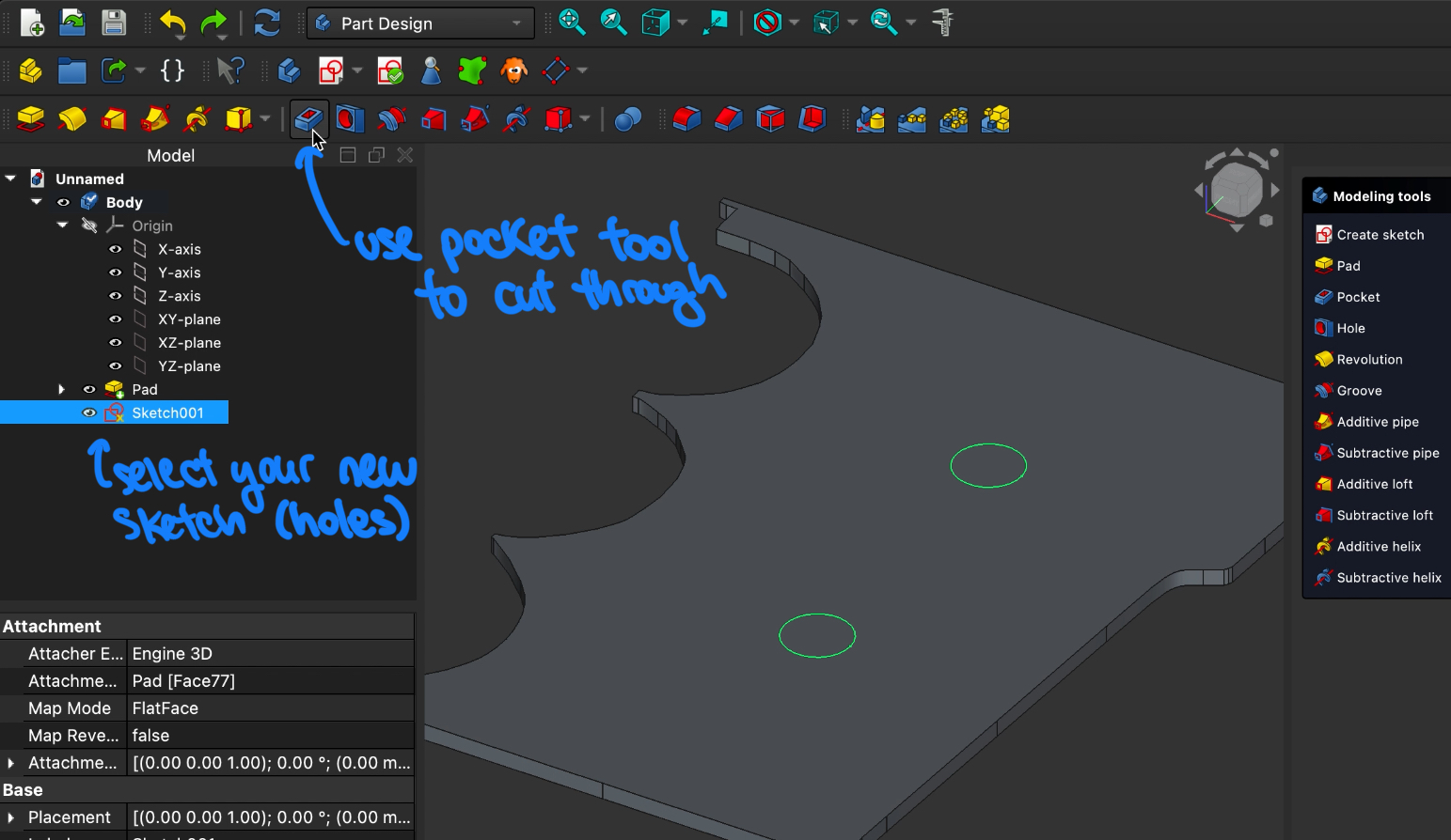
Once you are happy with the placement of the holes, exit the sketch and go back to the Part Design workbench. With the sketch selected, click the Pocket tool button to cut through your design. Just make sure here that the depth of the pockets are equal or greater than the thickness of your rib.
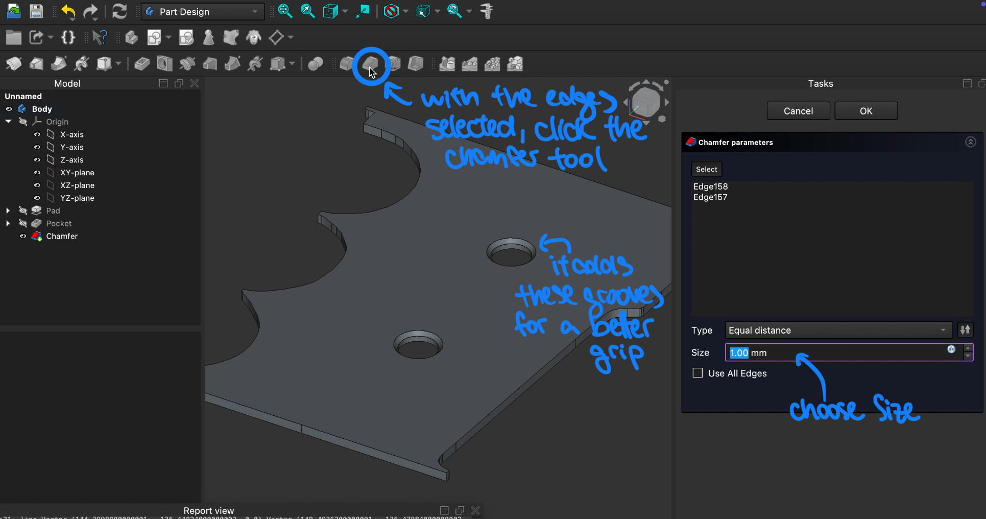
Another optional thing to add to your tool is chamfers. These basically smoothen out the edges for a better grip. With the edges of the holes selected, click on the Chamfer button in the toolbar and choose an appropriate size.
 Also, if your computer is stronger than my 5-year-old Macbook, it might be able to handle chamfering the entire rib. I tried this several times and crashed the program every single time… (I miss my lab-assigned computer with GPU and Solidworks :( )
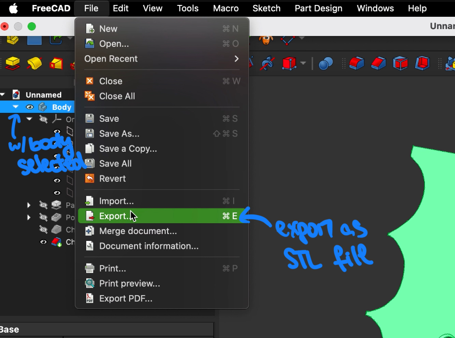
Finally, it is time to export your 3D model as an STL file. Make sure the body is selected when you do this step:
3D Printing and final result
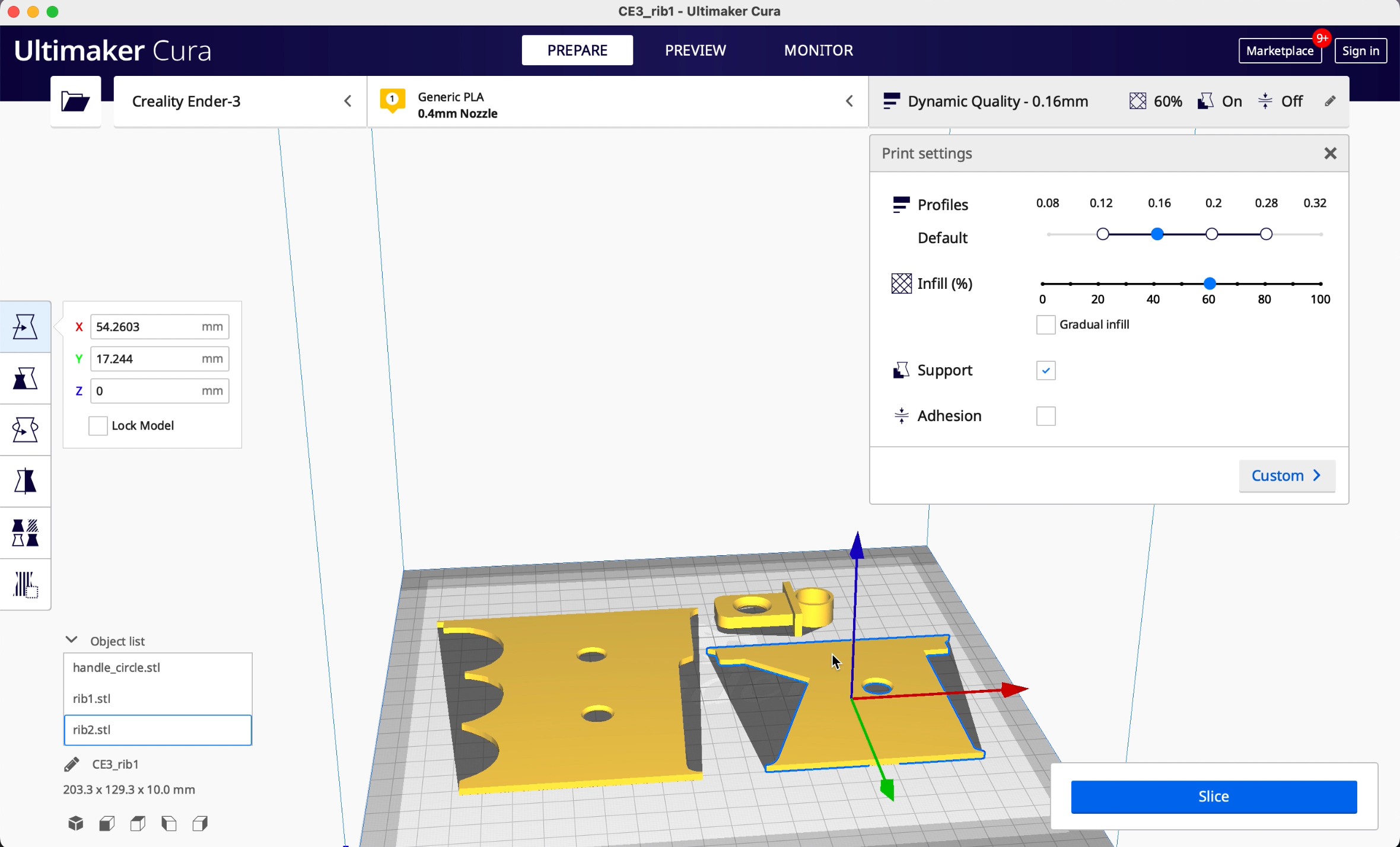
As always, use a slicer tool to convert your STL file into language that your printer can understand. I use Ultimaker Cura, but there are plenty of options out there.
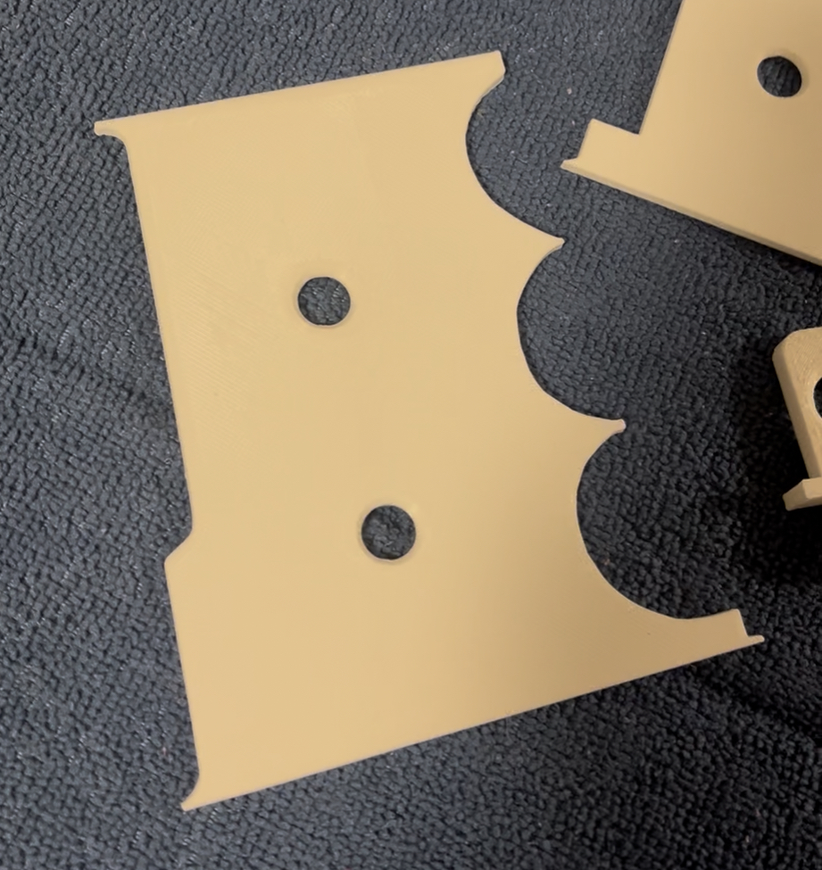
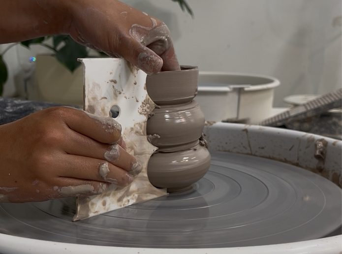
Here is what my rib looks like after it is printed! I personally find that the edges in-between the bubbles are a bit too sharp and can cut through the clay easily. In my next iteration, I will definitely be smoothing those spots. Also, the curvature can be reduced a bit too.
Overall, this was a fun experiment. Please give it a try and let me know how you would improve it! I would love to hear your ideas :)